3B Line Follower Robot

A fully autonomous robot that follows a marked course, locates a target using computer vision, and retrieves and delivers it to a safe zone — built from the ground up across mechanical, electrical, and software design.
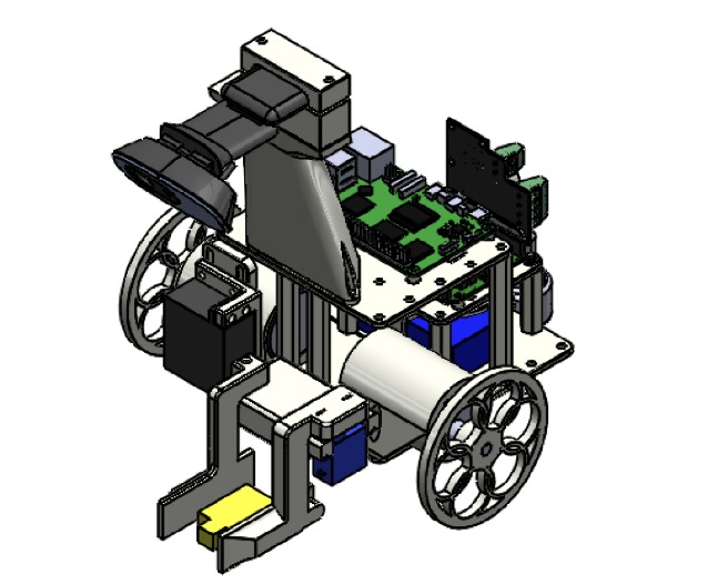
Overview
LAH (Line-tracking Autonomous Hemipode) was my team's capstone-style project for MTE 380: Mechatronics Engineering Design Workshop at the University of Waterloo — a five-person, term-long design challenge to build a fully autonomous robot capable of completing a "search and rescue mission" on a 6ft-by-6ft course, entirely on its own.
The robot had to follow a red line from a start position, locate a LEGO minifigure placed inside a red/white/blue target, pick it up, carry it to one of two green safe zones, drop it off, and return to the start — all without deviating from the line, falling into obstacle pits, or any human interference. The whole build was constrained to a $300 budget, a 0.22m × 0.22m × 0.25m footprint, and a 5 lb (2.27 kg) weight limit.
Specs at a glance
| Mission | Autonomous line-following, target retrieval, and delivery on a 6ft × 6ft maze course |
| Chassis | 3D-printed, stacked-plate design (base / motor-control / vision plates) |
| Vision | Webcam + Raspberry Pi 5, OpenCV color/line detection, PID-driven steering |
| Compute | Raspberry Pi 5 (vision + control logic) → Arduino Uno (motor/servo execution) over USB serial |
| Drive | 2× DC motors, differential drive, Adafruit Motor Shield |
| Gripper | 2-servo lift-and-clamp mechanism |
| Power | Single 3S 11.4V LiPo battery, custom-designed buck converter PCB for the 5V/5A electronics rail |
| Result | 1.2 kg, $183.03 (under the $300 budget), 6th place overall — best run completed in ~13.6s to target |
How I Built It
Software: vision and control
The robot's "brain" was a Raspberry Pi 5 running an OpenCV pipeline that tracked the red course line in real time, feeding a custom PID controller class that could be re-tuned independently for line-following versus precision alignment during pickup/drop-off. Color ranges were defined in HSV so the vision system could tolerate lighting changes between our private test course and the actual competition floor. The Pi talked to an Arduino Uno over USB serial, sending simple left/right motor speed commands and predefined trigger characters for the gripper sequences — keeping all low-level motor and servo control off the vision system entirely.
Pickup and drop-off were built as scripted sequences: on detecting the target's blue ring, the robot stopped, used two synchronized PID loops (forward and rotational) to align the gripper precisely over the LEGO figure, then executed a fixed lift-and-clamp motion before reorienting to re-find the line. Drop-off followed a similar scripted approach triggered by the blue square marking the safe zone.
Mechanical: chassis and gripper
The chassis was a stack of three 3D-printed plates on standoffs, each with a grid of mounting holes so components (motors, battery, Arduino, Raspberry Pi, gripper, camera mount) could be repositioned or swapped without redesigning the whole structure. The gripper went through a full redesign mid-project: the original single-motor leadscrew-and-rope "drawbridge" concept was more weight-efficient but too dependent on precise assembly to be reliable, so the team pivoted to a proven two-servo lift-and-clamp design instead. Wheels were 3D-printed and switched from four wheels to two driven wheels plus a metal caster to improve turning radius and cut weight.
Electrical: consolidating onto one battery
Rather than the kit-provided approach of a separate USB power bank for the electronics, the team designed a custom buck converter PCB in KiCad to step the 11.4V LiPo battery straight down to a regulated 5V/5A rail for the Raspberry Pi, while raw battery voltage still fed the motor shield directly. That decision — a full custom PCB instead of an off-the-shelf regulator module — traded extra design and layout work for a lighter, more integrated power system, and shaved about 200 grams off the robot.
(Full write-up of the power electronics design is broken out separately: 12V → 5V Buck Converter.)
Challenges
Lighting sensitivity in the vision system was a recurring problem — the same colors read differently under different ambient light, and the target's blue ring in particular sometimes failed to trigger the pickup sequence. Sharing one battery between the Pi and the drive motors also introduced a subtler issue: as the battery drained during a run, motor response and stability shifted, making tuning inconsistent from test to test. Physically, the battery lived at the bottom of the stacked chassis, so every swap meant partially disassembling the robot — a real drag on iteration speed during tuning. On Game Day itself, gripper servo wiring that had been routed in front of the mechanism got caught and snapped during the first run; a backup servo saved the remaining attempts.
Accomplishments
The team shipped a fully integrated robot — mechanical, electrical, and software — on schedule and under budget at $183.03 against a $300 cap, all while staying within the size and weight limits. The custom buck converter alone cut roughly 200 grams versus the kit-provided power bank approach. On its one clean run, the robot completed the full course (line-following, target retrieval, and delivery) in about 13.6 seconds to the target, closely matching the team's own pre-competition estimates, and placed 6th overall in the competition.
What I Learned
Beyond the technical skills — PID tuning, OpenCV-based color/line detection, switching-regulator PCB layout, IPC-2221 trace sizing — the biggest lesson was about integration risk. Most of the problems that showed up on Game Day weren't failures of any single subsystem; they were second-order interactions between subsystems (shared battery drain affecting motor behavior, cable routing conflicting with gripper motion, lighting assumptions baked into vision tuning) that only surfaced once everything was combined and tested as a full system.
What's Next
A chassis redesign with an easily accessible battery slot would have saved an estimated 5+ hours of disassembly/reassembly over the course of the project. On the vision side, adding a fixed, bright light source near the gripper would reduce the system's sensitivity to ambient lighting conditions. And on the power side, gathering real efficiency and thermal data on the buck converter under sustained load would help characterize it beyond the bench validation it got before competition.