Custom Buck Converter Module
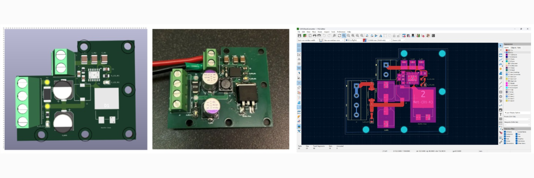
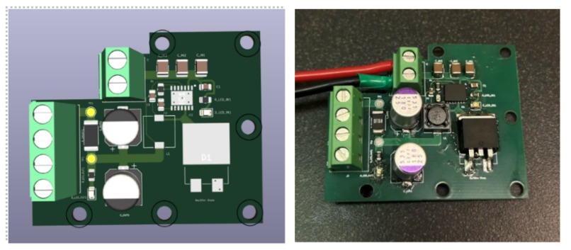
A custom KiCad-designed switching regulator PCB that steps an 11.4V LiPo battery down to a regulated 5V/5A rail — built to power a Raspberry Pi 5 and control electronics on an autonomous line-following search-and-rescue robot.
Overview
Built for MTE 380: Mechatronics Engineering Design Workshop at the University of Waterloo, this board was the electrical backbone of a capstone project: a fully autonomous robot that had to navigate a maze, locate a target, and carry it back to a safe zone, all under a $300 budget and tight size and weight constraints. (The robot itself is written up separately: 3B Line Follower Robot.)
The robot ran on a single 3S 11.4V LiPo battery. Rather than carrying a separate USB power bank to feed the Raspberry Pi 5, an Arduino Uno, a webcam, and the rest of the control electronics, I designed a custom buck converter to regulate the main battery down to a clean 5V/5A rail — consolidating the entire power system onto one battery, cutting weight, and simplifying the wiring harness. Raw battery voltage still routes separately and directly to the motor controllers.
Specs at a glance
| Input | 8V–40V (11.4V nominal, 3S LiPo) |
| Output | 5V regulated, up to 5A continuous |
| Topology | Synchronous-adjacent buck converter, TI datasheet reference design |
| Fabrication | 1 oz copper, ~2mm power traces (IPC-2221 sized for 25W max), continuous ground plane |
| Regulator IC | LM2679SD-5.0/NOPB — 8V–40V, 5A step-down switching regulator (Texas Instruments) |
| Rectifier | VS-6TQ045S-M3 — 45V, 6A Schottky diode, D2PAK (Vishay) |
How I Built It
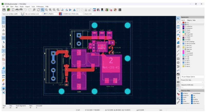
The schematic and PCB were designed from scratch in KiCad, built around the LM2679SD-5.0/NOPB switching regulator's datasheet-recommended application circuit. Layout followed Texas Instruments' SNVA054C SIMPLE SWITCHER PCB Layout Guidelines and the LM2679 datasheet:
- Component placement minimizes the high-current switching loop — the regulator IC, inductor, Schottky diode, and input/output capacitors are clustered tightly together to reduce parasitic inductance, with input capacitors placed right at the regulator's input pins.
- Routing keeps the battery input and 5V output traces short and direct to limit voltage drop, while the switching node is kept compact and isolated from signal traces to reduce noise coupling.
- Ground plane is continuous across the board, giving both the power and signal paths a low-impedance return.
- Trace widths on the high-current paths (~2mm) were sized using IPC-2221 guidelines for a 5V/5A, 25W maximum load.
Challenges I Ran Into
Sharing a single battery between the Pi and the drive motors turned out to have real second-order effects: current draw was faster than expected, and motor behavior shifted noticeably as battery voltage sagged under load — something that wasn't fully characterized before Game Day. Descoping the board to handle power distribution only (rather than more ambitious features) also pushed back procurement and assembly timelines. On top of that, the battery lived at the bottom of the chassis, so every swap meant partially disassembling the robot.
Accomplishments
A fully custom switching regulator PCB, designed, fabricated, and assembled in time for competition day. Consolidating onto a single battery eliminated roughly 200 grams of weight and meaningfully simplified the robot's wiring.
What I Learned
Hands-on experience with switching regulator layout, sizing traces against IPC standards, and designing ground planes for both electrical and thermal performance — plus a clearer sense that consolidating power sources introduces effects (like shared-battery voltage sag) that are worth planning for early rather than discovering during testing.
What's Next
Redesigning the chassis with an accessible battery slot, and gathering real efficiency and thermal performance data on the converter under sustained load.
Status / Known Limitations
- Validated on the bench and used successfully on Game Day, but battery voltage sag under load wasn't fully characterized — output behavior at low state-of-charge remains an open item.
- No onboard reverse-polarity or overcurrent protection beyond the regulator IC's internal current limiting.
- Designed for a single fixed 5V/5A rail; not currently configurable for other output voltages.